|
CALPOLY MECHATRONICS
Documentation for all Mechatronics Labs
|


|
|
CALPOLY MECHATRONICS
Documentation for all Mechatronics Labs
|
|
As the final project for Calpoly's Intro to Mechatronics class I created a set of drivers and tasks to control the position and velocity of a brushed DC motor using closed loop feedback and a PID controller.
The motor is controlled with a Nucleo board and programed using micropython.
The documentation for this project is divided into four weeks:
The final goal of this project was to have a motor track a reference position and velocity profile and send the actual position and velocity back to a connected PC via serial for plotting.
More specifically, the Nucleo receives closed loop feedback #from an encoder connected to the motor by a belt and pulley, which is decoded using the encoder driver created in week 2. The closed loop feedback is then fed to a controller task, created in week 3 and week 4, which determines how the motor should be powered to track a reference profile. The controller output is then fed to a motor driver, created in week 2, which controls the motor power using PWM. Finally, a serial communication task created in weeks one and four, sends the actual motor position and velocity to a connected PC over serial for plotting.
There was significant friction in the pulleys that caused the calculated proportional gain of the controller to be far to low for the real life system, as discussed in week 3. To improve the perforamnce of the PID controler, I created a method, controller.Controller.selfTune(), which repeatedly subjects the motor to a step input and incrementally varries Kp and Ki to minimize the J value of the controller. Note that Kp and Ki here is proportional gain relative to the position error, not the velocity error as previously calculated. For the full PID controller taking the position error signal as an input, as implemented in week 4 Kd is actually equivalent to the kp for the P controller acting on a velocity error signal, as implemented in week 3.
The controller.Controller.selfTune() only tunes P and I values, wich results in a controler that performs only position control, not velocity control. The results of this PI controler are shown in figures 1 and 2 below.
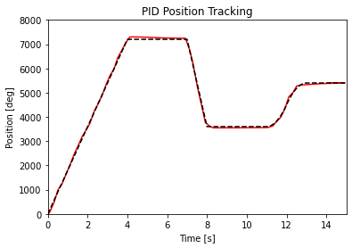
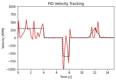
Based on the results show above, PI control is capable of tracking a position profile to a reasonable degree of accuracy; However, it's transient response is not smooth, which results in extremely poor velocity profile tracking. The total J value, a measure of how well the controller performs, was 6.5 (lower numbers are better). To improve the velocity tracking performance a full PID controller is needed, which can perform simultaneous position and velocity control. To create an effective PID controller, I added back in a Kd gain of 10 V/(rotation per second), which I experimentally found to be the best Kd value in week 3. The results of this full PID controler are shown in Figures 2 and 3 below.
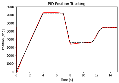
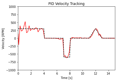
The full PID controller's transient response is much smoother, as seen by the smaller fluctuations in the velocity graph, while still maintaining accurate position control, something which is not possible with a velocity controller only. The J value of the full PID controller was 3.16, less than half that of the J value of the PI controller, which confirms that the PID controller is much more effective at acuratley controlling both position and velocity.