|
CALPOLY MECHATRONICS
Documentation for all Mechatronics Labs
|


|
|
CALPOLY MECHATRONICS
Documentation for all Mechatronics Labs
|
|
To interface with the motor I created a motor driver class, motorDriver.Motor which uses PWM applied to both leads of the motor to control the voltage to the motor.
The motor class is used by the controller task, controller.Controller to set the duty cycle of the motor.
Additionally, I created a proportional velocity controller (the D in PID) to control the motor's velocity. pid.closedLoop is a more advanced version of this controller that I developed in week 4. The proportional velocity controller uses a single proportional gain, Kp to turn the velocity error signal (desired - measured velocity) into a motor duty cycle (in percent). Note that because this controller was performing velocity control, and the PID controller I created in week 4 was performing position control the Kp value in this section is actually equivalent to the Kd value in week 4.
To find a starting value for Kp, I used the transfer function for a DC motor and solved for a Kp that would result in a steady state velocity error of less 5 percent. The calculations are shown in figure 1 below.
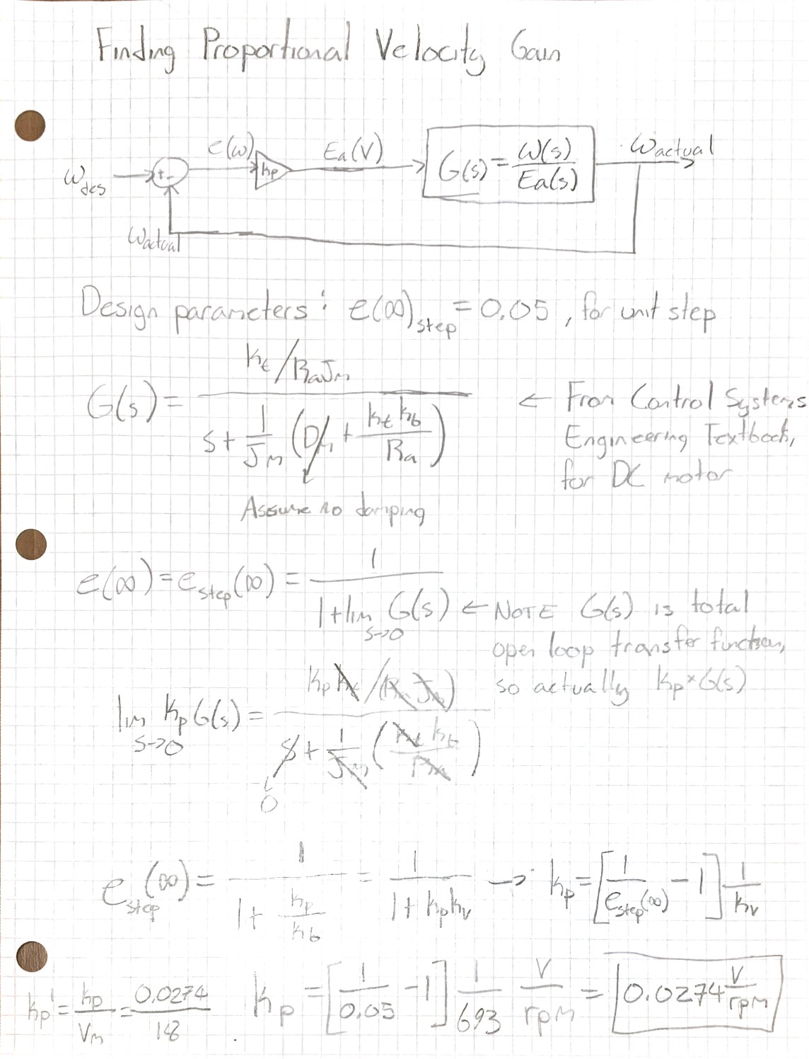
One of the major assumptions I made in these calculations was that there was no damping in the system. This assumption is not very good because the belt that connects the motor to the encoder creates so much friction That it stalls the motors above 75 percent duty cycle; However, I did not have a good way to measure the friction. These calculations yielded a Kp value of 0.001522 %/rpm for 5 percent steady state error.
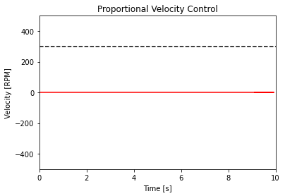
As expected, when I plugged this gain value into my controler and subjected it to a step input of 0 to 300 RPM, the gain was so low that the motor couldn't overcome the friction of the belt and never moved, shown in Figure 2 below.
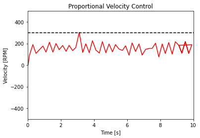
Next, I arbitrarily increased the the gain to 0.167 %/RPM (10 %/RPS, which is what my pid.ClosedLoop measures in). This was a large enough gain that the motor was able to nearly reach the target velocity of 300 RPM; However, due to the fact that the belt friction changes dramatically through one revolution, the system never came close to steady state because the friction torque the motor had to overcome was constant changing. The results of the step input with a gain of 0.167 V/RPM are shown below in Figure 3.
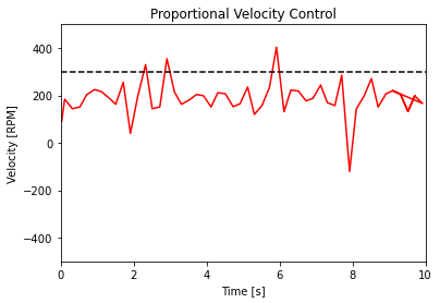
After trying a gain of 0.33 %/RPM (20 %/RPS), shown in Figure 4 below, I settled upon a gain of 0.2 %/RPM (12 %/PRS).
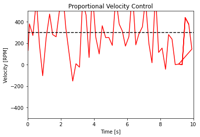
At 0.2 %/RPM, the motor averaged a speed near the target velocity of 300 RPM, shown below, which was the best I could hope for given the unsteady loading on the motor.
Although I would have liked to use the controller J values to compare them, the motor speed was fluctuating so much that even between runs of the same controller the J values would fluctuate by nearly an order of magnitude. For reference, the J values of the best controller with a gain of 0.2 %/RPM were arround 500, while the J value for the best PID controler I made in week 4 was 3.16.